

When it comes to specifying fans for fume extraction, specifiers face a multitude of considerations to address, from design intricacies to system integration in order to ensure fume fans align with project requirements and contribute to the overall effectiveness of fume extraction systems. Precision and efficiency are of paramount importance to ensure the safety and well-being of occupants in industrial and laboratory settings.
This article covers the capabilities of Building Information Modeling (BIM), Computer-Aided Design (CAD), and Standard for the Exchange of Product Data (STEP) files in elevating the precision of fume fan specification. By harnessing the power of these advanced digital tools, specifiers can unlock a new level of accuracy, coordination, and collaboration in fume extraction system design, ultimately leading to safer, more efficient, and compliant environments.
BIM files, also known as Building Information Modelling files, are digital representations of a product, building or infrastructure project that contain valuable information about the project’s design, construction, and operation. BIM files are used extensively in the architecture, engineering, and construction industries. Specifiers, such as architects, engineers, and contractors, often require BIM files for several reasons:
Visualisation and Design: BIM files provide a 3D visual representation of the product, building or structure, allowing specifiers to better understand the design and spatial relationships. This helps them make informed decisions during the planning and design phases.
Coordination and Collaboration: BIM facilitates collaboration among various project stakeholders. Specifiers can integrate their design components with other disciplines, such as structural and mechanical systems, to ensure compatibility and identify potential clashes or conflicts.
Data-Rich Information: BIM files include detailed information about the project’s components, materials, dimensions, and specifications. This data-rich approach allows specifiers to access critical information for accurate cost estimation, material selection, and performance analysis.
Clash Detection and Clash Resolution: Using BIM files, specifiers can perform clash detection analysis to identify clashes or interferences between different building elements. Resolving clashes during the design phase helps avoid costly rework during construction.
Sustainability and Performance Analysis: BIM files can be used to analyse the energy performance, thermal behaviour, and sustainability aspects of a building. Specifiers can make data-driven decisions to optimize energy efficiency and environmental impact.
Construction Planning and Sequencing: BIM files can aid in construction planning and sequencing. Specifiers can visualize the construction process, plan logistics, and identify potential construction-related issues in advance.
Facilities Management and Maintenance: BIM files provide valuable data for facilities management after construction. Specifiers can hand over the BIM model to facility managers for better maintenance planning and asset management.
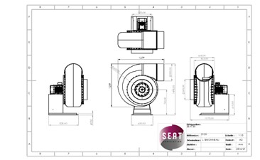
At Axair Fans, providing BIM files for corrosion resistant fans to specifiers, allows for enhanced collaboration, reduces errors, and streamlines the entire construction process from design to facilities management. STEP and CAD files are available on request to facilitate seamless integration into specification documents.
The more popular choices for specifiers in fume fan selection are typically Computer-Aided Design (CAD) files and Standard for the Exchange of Product Data (STEP) files. Both of these file formats offer specific advantages to specifiers during the fume fan selection process CAD (Computer-Aided Design) and STEP (Standard for the Exchange of Product Data) files are both digital file formats used in the engineering and manufacturing industries to represent 3D models. While they serve similar purposes, they have some key differences:
File Format:
- CAD: CAD files come in various formats specific to the software used to create them. Examples include DWG (AutoCAD), SLDPRT (SolidWorks), and IPT (Autodesk Inventor).
- STEP: STEP is an industry-standard file format, defined by ISO 10303, that allows the exchange of product data between different CAD software and systems.
Compatibility:
- CAD: CAD files are generally proprietary to the software that created them. While some CAD software can import files from other CAD programs, compatibility can be limited, and some data may be lost during the transfer.
- STEP: STEP files are designed to be platform-independent and promote interoperability between different CAD systems. They are widely accepted by most CAD software, ensuring better compatibility and data retention during data exchange.
Data Representation:
- CAD: CAD files are typically saved in a format specific to the software, containing geometric data, model features, assembly relationships, and material information. The level of detail and the data included can vary depending on the software’s capabilities and the user’s choices.
- STEP: STEP files use a neutral data structure to represent the 3D model. They contain precise geometric data, surface representations, assembly hierarchies, and product structure information. STEP files aim to preserve the design intent and provide a complete representation of the model.
File Size:
- CAD: CAD files can sometimes be larger in size due to the inclusion of proprietary data and additional information specific to the software.
- STEP: STEP files tend to be more compact since they use a standardised data format without any proprietary information, resulting in a more streamlined representation of the 3D model.
Industry Adoption:
- CAD: Different industries may have specific preferences for CAD software, leading to variations in the types of CAD files used.
- STEP: STEP files have gained widespread adoption and are commonly used for data exchange in industries with diverse CAD software usage, ensuring seamless collaboration between different stakeholders.
In summary, CAD files are specific to individual CAD software and may not be universally compatible, while STEP files provide a standardized, platform-independent format for exchanging 3D model data between different CAD systems. STEP files are preferred for data exchange to ensure consistency and efficient collaboration across various engineering and manufacturing processes.
Specifiers can utilise BIM, CAD, and STEP files in various ways during the fume fan selection process to ensure an efficient and accurate design for fume extraction systems. Here’s how each file format can be employed:
BIM Files:
- Visualisation:BIM files allow specifiers to visualise the entire building or facility in a 3D model, including the layout of the fume extraction system, ductwork, and placement of fume fans within the structure.
- Clash Detection:BIM facilitates clash detection to identify potential interferences or conflicts between the fume extraction system components and other building elements. This helps avoid design errors and ensures proper space allocation for the fume fans.
- Integration with Other Disciplines:Specifiers can integrate the fume extraction system BIM model with other building systems, such as HVAC and electrical, to ensure coordination and compatibility.
- Quantities and Cost Estimation:BIM allows specifiers to extract quantities of materials and components, aiding in accurate cost estimation for the fume fan selection.
CAD Files:
- Detailed Design:Specifiers can use CAD files to delve into the detailed design of individual fume extraction system components, such as fans, ductwork, hoods, and diffusers.
- Customisation:CAD files enable specifiers to modify and customise the fume fan models according to specific requirements or site constraints, ensuring a tailored solution for the project.
- Engineering Analysis:CAD files can be used for engineering analysis, such as stress testing or flow simulations, to ensure the fume fans can handle the anticipated airflow and pressures.
STEP Files:
- Interoperability:Specifiers can use STEP files to exchange fume fan models between different CAD software platforms, ensuring seamless collaboration with various stakeholders.
- Vendor Comparison:Specifiers can obtain STEP files from different fan manufacturers, allowing for direct comparisons of fan specifications, sizes, and performance characteristics.
- Integration with BIM/CAD:STEP files can be imported into BIM and CAD software for integration into the overall fume extraction system design.
By leveraging BIM, CAD, and STEP files, specifiers can achieve a comprehensive and data-rich design for fume extraction systems. These file formats facilitate collaboration, streamline the design process, aid in system analysis, and ensure a seamless flow of information among stakeholders, ultimately leading to a well-optimised and effective fume fan selection.
For more information call Axair Fans on 01782 349 430 or alternatively you can speak to a member of the technical team on Axair’s live web chat.
For more information on Fume Fan Specification Using Advanced Digital Tools talk to Axair Fans UK Ltd