Sign In


Components Of An Ultrasonic Welding System
28-08-2017
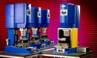
The press in an ultrasonic welding system provides the necessary force that must be applied during the welding process. A mounting is provided to carry the transducer/booster/sonotrode assembly often collectively referred to as ‘the stack’. The application of a controlled force is critical in any ultrasonic welding application, as the power drawn from the generator is directly affected by the applied pressure. The press must therefore provide a rigid mounting and an accurately applied downforce. With very few exceptions all ultrasonic welding presses are pneumatically operated, the fact that air cylinders provide an exponential rise in force when compared to time is often beneficial to the welding process. Some modern presses also have the option of an attached linear encoder to further enhance the control of welding depth.Summary of primary features
Rigid mechanical design
Low friction slide mechanism
Force capability 50 – 3000N
Accurate stroke adjustment
Adjustable mechanical stop
High accuracy pressure regulation and speed control
Most standard production presses feature a two-hand start system to provide the necessary operator safety. Machines with sliding tables and fully enclosing guarding provide a higher degree of safety as third party protection is also provided. For applications where high levels of noise can be generated from the components being welded it may be necessary to provide a local or fully enclosing acoustic booth.
The Generator
The generator in an ultrasonic welding system converts the mains 50-60 Hz supply into an ultrasonic frequency of 20-50 kHz depending on the power rating of the generator, it can be designed to operate from a single or three phase supply. The generator provides the power for the welding operation and is therefore a critical feature of the machine. It must be capable of providing a very consistent output amplitude and be resistant to overload.
Summary of primary features
Consistent amplitude at all power levels – the power draw on the generator varies considerably during the welding process, the generator must be capable of providing a very consistent level of amplitude to ensure quality levels of the welded components are maintained.
Accurate frequency control – the output frequency of the generator must match the resonant frequency of the tooling being used. This frequency must also be accurately maintained in order to prevent unnecessary stress in the tooling and transducer. If the frequency is not correctly controlled it can lead to premature failure of the tooling and/or transducer.
Overload protection – the power drawn from an ultrasonic generator is directly affected by the pressure applied during the welding operation. Excessive press pressure setting or incorrect loading of component into a nest can result in the power demand from the generator exceeding its capabilities.
The generator needs to be fitted with the necessary fast acting overload protection circuitry in order to prevent these overload conditions having a detrimental effect on the generator.
Automatic tuning – the resonant frequency of the sonotrode varies during the welding cycle due to the effects of pressure, heat and wear. These changes need to be compensated for by altering the output frequency of the generator to match the variations in the tooling.
High duty cycle – many ultrasonic welders, particularly in automatic machines, operate at up to 60 welds per minute with typical weld times of half a second or more. The generator must be capable of sustaining this duty cycle whilst at the same time maintaining its output characteristics.
Screening against electromagnetic interference – this is a statutory requirement in all European countries.
The provision of a digital frequency display provides a useful means of checking the resonant components for faults and frequency variations.
The Transducer
The transducer changes the applied ‘vibrating’ electrical signal into a mechanical vibration. This is achieved by use of a sintered ceramic PZT (lead-zirconate-titanate) material which produces a change in thickness when a change in electrical polarisation is applied. The change in thickness is very small, in the order of 1-3?m. To produce a movement large enough to be of use in the welding operation a number of discs of PZT are used in one converter. PZT materials are exceptionally efficient in converting electrical energy into mechanical vibration, typically more than 95%. This enables the heat increase in the converter to be kept to a minimum.
Early ultrasonic welding machines were developed using metals that exhibit a change in length with changes in polarisation. These types of materials are known as magnetostrictive. Due to their much lower efficiency in converting energy virtually all ultrasonic equipment now uses PZT materials.
The Booster
The booster transmits the energy from the converter to the sonotrode. The amplitude of the mechanical vibration can also be amplified during its passage through the booster. This amplification is achieved by varying the mass at each end of the booster usually by introducing a step in diameter at its nodal (centre) point.
A range of standard booster ratios is available to enable the correct amplitude to be generated at the welding face of the sonotrode.
The Sonotrode
The sonotrode transmits the welding energy directly into the components to be welded. The design of the sonotrode is dependent on a number of factors including the following:
Amplitude, gain required
Frequency
Material to be welded
Sonotrode material
Profile or form of component
The stress levels in sonotrodes affect the durability of the tool in use and physical dimensions are restricted by the frequency.
Materials
Aluminium – only high strength alloys are suitable. Due to its soft nature aluminium sonotrodes are only suitable for applications where wear is not likely to occur or is not a concern, i.e. for experimental sonotrodes or welding unfilled materials.
Titanium – most commonly used material for high volume welding work. Titanium has the capability to withstand higher stress levels than aluminium and can therefore be used for sonotrodes requiring high gain and wear resistance.
Steel – acoustically not such a good material, results in sonotrodes with higher losses and stress. The fact that this material can be hardened to withstand high levels of wear makes it suitable for inserting applications and welding of glass filled materials. Special grades of sintered or powder metallurgy steels are also used for some special welding applications.
Types Of Sonotrodes
Stepped cylindrical – the most common type, cheapest to manufacture, different diameter at each end to provide the required gain.
Exponential cylindrical – development of the above with exponential shape to reduce the stress in the sonotrode, has lower gain capability.
Catenoidal cylindrical – combination of stepped and exponential, reduced stress and moderate gain.
Mother/Daughter – assembly of smaller sonotrodes onto a large block sonotrode to enable a number of sonotrodes to be run on a single system.
Bell – sonotrodes with the centre bored out to provide gain, allows the use of the maximum sonotrode diameter for welding.
Block – rectangular sonotrode, no gain, for welding large flat components.
Blade – rectangular sonotrodes with gain suitable for long or narrow welds.
Slotted – cylindrical, bell, block or blade sonotrodes above certain sizes need to be slotted to eliminate spurious frequencies being developed in sonotrode which would be detrimental to their operation.
The gain in a sonotrode can generally be determined by expressing a comparison of the surface area at the end of the sonotrode as a ratio.
Further information on sonotrodes is given in the sonotrode design section of this course.
The Nest/Jig/Anvil
The way in which the component is nested during welding can be critical to the success of the welding operation. The assembly must be located to allow free movement between the two components to be welded. Accurate positioning of the nest in relation to the sonotrode is particularly important where the sonotrode is designed to locate around features on the moulding. To a great extent the choice of nest material will be determined by the material, size and shape of the assembly to be welded. As some materials transmit ultrasonics more readily than others, consideration must be given to the possibility of the components being damaged due to vibration being generated between the component and nest. This problem can usually be overcome by lining the nest with a suitable material, such as, cork or urethane sheet. An alternative to lined nests is to cast the nest in a resin material, this has the benefit of making a nest perfectly match the part, whilst at the same time providing a damping material under the component to prevent marking.
Controls
Since the introduction of ultrasonic welding the advances in electronic technology have been tremendous. It is now possible to very accurately control the weld and cool times during a welding process. It is also possible to measure the energy transmitted to the assembly and hence to vary the weld time so that every assembly receives the same amount of energy. Depending on the welding application, the most appropriate control system can be selected.
For more information on Components Of An Ultrasonic Welding System talk to Xfurth Ltd
More News
Welcome back to FindTheNeedle.
Not registered? Get listed — most visitors don't have an account yet.
List your company on FindTheNeedle.