Sign In

Sealing an Anti-Air Warfare Destroyer
02-08-2007
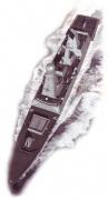
On the eve of the scheduled launch of the first of the Royal Navy's Type 45 Daring Class Anti-Air Warfare Destroyer, MER takes a detailed look at the composite bearing materials specified onboard
The Type 45 Anti-Air Warfare Destroyer will provide air defence cover for the Royal Navy and will replace the Type 42 destroyers in service.
The deep displacement is circa 7350t with a length of 152.4m and a beam of 21.2m.
The water Iubricated shaft bearings comprise the Main 'A' Bracket bearings and Intermediate bearings. Port and starboard shafts are of different lengths.
Because the shaft loading geometry has a large variance between the cold (static) condition and the warm (MCR) condition together with the length of the 'A' Bracket Barrel a computer program was developed to assess the bearing loading under both conditions.
The shaft bearings are required to operate at extremely low shaft revolutions and therefore cannot rely on the hydrodynamic lift induced by the shaft rotation; Orkot TXMM was selected as this material has low friction under boundary lubricated conditions.
The other requirements were that the bronze bearing housing should remain fitted in the bracket barrel under refit and that the bearings should be capable of being removed without dry-docking in an emergency.
Three segments
The bearings are in three segments with the bottom segment forming a 140deg arc, for good hydrodynamic performance. The bearing pressure was limited to around 5.5 bar but in reality this will vary due to the variable shaft angle from cold to MCR.
The segments are locked in position with a removable key assembly which is easily accessed with the front retaining ring removed. The key can be withdrawn as a self-contained assembly allowing each segment to be removed.
The bearing segments are machine-finished, which removes the need for any machining or work in the shipyard.
The Main 'A' bracket bottom segment is designed from the computer program to allow for elastic deformation. This eases bedding in by increasing the contact footprint and reducing the edge loading, because the shaft angle changes from positive to negative from static to MCR.
As the aft bracket barrel is longer than required for bearing requirements, and to reduce the effects of the shaft angle, the forward third of the bearing length is relieved as a safety bearing.
One requirement for the intermediate bearing is that the propulsion shaft has to be removed at an angle and therefore the bronze housing has two location diameters with the smaller diameter fitted into a removable bronze housing at the other end of the barrel. This allows the shaft to be tilted for removal within the length of the vessel.
Both the intermediate and aft bearings were fitted with thermocouples to monitor the bearing surface temperature during the basin trials. The reason is that for these trials the resistance to the propulsion motor is by brake blades fitted in place of the normal propeller blades. Since brake blades do not induce thrust there is no propeller lift to reduce the bearing pressure.
For any water lubricated bearing a period of running in is required to form the optimum running surface for hydrodynamic operation. As crude torque measurements are not sufficient to determine when the bearing is operating in this mode, thermocouples were fitted into the bearing to moiiltor bearing surface temperature.
Coupling protection
The shaft protection covers are designed to protect the hydraulic coupling which joins the propulsion shafts together from seawater corrosion.
Corrosion on the coupling nut and taper sleeve can prevent the normal disassembly of the coupling on refit and severe corrosion on the body of the coupling will reduce the hoop Stress induced by the taper sleeve.
Prior to this, aluminium cones and rubberised protective coverings were used. The effects of the shaft t
For more information on Sealing an Anti-Air Warfare Destroyer talk to Trelleborg
Welcome back to FindTheNeedle.
Not registered? Get listed — most visitors don't have an account yet.
List your company on FindTheNeedle.